Showing posts with label 8085 microprocessor. Show all posts

Friday, 3 June 2016

8085 microprocessor


The Intel 8085  is an 8-bit microprocessor produced by Intel and introduced in 1976.This was the most advanced and developed computing chip produced at that time.

In this blog I will explain everything about microprocessor that you need to know as per your school and college needs and I will also cover up some Assembly language programs for practicals.


CONTENT'S(click on the topics below)
  • Introduction to 8085
    • What is a microprocessor?
    • What are its application in general life?
    • 8085 microprocessor and its features.
  • Concept of Address,Data and Control Bus
    • What is an Address Bus?
    • What is a Data Bus?
    • What are control bus?
  • PIN Diagram
    • 40 PIN functional layout of 8085 (diagram)
    • Address Bus(A8-A15)
    • Multiplex Address/Data Bus(AD0-AD7)
    • Control and Status signal
    • Power supply and clock frequency signals
    • Interrupts and peripheral initiated signal
    • Serial I/O signal
  • Architecture of 8085
    • Architecture diagram of 8085
    • Timing and control unit
    • Arithmetic and Logic Unit 
    • Address and Data Buffer
    • Instruction Register and Decoder
    • CPU Register Array
    • Interrupt control
    • serial control
  • 8085 programming
    • Types Addressing modes
    • Types Instruction set
    • All instructions with examples
  • Assembly language programs and common practicals


Thursday, 5 May 2016

Register array

Register array:
     There are various types of registers in 8085.These registers are used for storage ,manipulating data and instructions.The different types of registers are:

  1. Accumulator.
  2. Temporary register.
  3. General purpose register.
  4. Program Counter.
  5. Stack Pointer.
  6. Instruction register.
  7. Flag register.


Accumulator:-It is a 8-bit register which is used to perform arithmetical and logical operation. It stores the output of any operation. It also works as registers for i/o accesses.

Temporary Register:-It is a 8-bit register which is used to hold the data on which the acumulator is computing operation. It is also called as operand register because it provides operands to ALU.

General purposes registers:-Microprocessor consists 6 general purpose registers of 8-bit each named as B,C,D,E,H and L. Generally theses registers are not used for storing the data permanently. It carries the 8-bits data. These are used only during the execution of the instructions.
      These registers can also be used to carry the 16 bits data by making the pair of 2 registers. The valid register pairs available are BC,DE HL. We can not use other pairs except BC,DE and HL . These registers are programmed by user.

Program Counter:-It is a 16 bit register used as memory pointer. It stores the memory address of the next instruction to be executed. So we can say that this register is used to sequencing the program. Generally the memory have 16 bit addresses so that it has 16 bit memory. The program counter is set to 0000H.

Stack Pointer:-It is also a 16 bit register used as memory pointer. It points to the memory location called stack. Generally stack is a reserved portion of memory where information can be stores or taken back together.

Instruction registers :-It is a 8-bit register. When op-code of an instruction is fetched from memory then it is stored in this register. This is not programmable and is not available to he programmer.

Flag register:-It contains 5 single bit flags and three unused bits which changes its status according to the result stored in an accumulator

Reset signals

RESET Signals:


  1. Reset in (PIN 36): This is active low input. This pin is used to reset the microprocessor. An active low signal applied to this pin reset the program counter inside the microprocessor. The buses are tri-stated.
  2. Reset out (PIN 3): If we want to reset the external devices connected to the microprocessor then a signal applied to this pin resets the external devices.

Hardware interrupts

       8085 has five hardware interrupt signals that can be used to interrupt program execution.these signals are
            (1)TRAP
            (2)RST 7.5
            (3)RST 6.5
            (4)RST 5.5
            (5)INTR/INTA


TRAP (PIN 6):
    Trap is highest priority, nonmaskable interrupt, when trap is received microprocessor starts the program execution from location (4.5*8) =0024H. this is why it is also called as vectored interrupt.

RST 7.5, 6.5, 5.5 (PIN 7,8,9):
     These are restart interrupts or vectored interrupt. these are maskable interrupt and has lower priority than TRAP, among these RST 7.5 has the highest priority and RST 5.5 having the lowest.

INTR (PIN 10):
    Interrupt request - this signal is used as a general purpose interrupt.it has lowest priority and is a maskable interrupt.

INTA (PIN 11):
     This is interrupt acknowledgement signal sent by the processor when INTR is recognized. This is active low signal.

Bus


BUSes:-


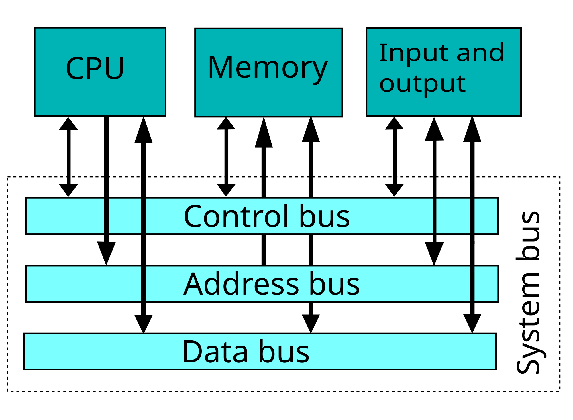
1.What is an Address Bus?
         The Address bus is unidirectional i.e. information flows in one direction only from microprocessor to device only.microprocessor uses this bus to identify peripherals or memory locations.The memory locations or peripheral is identified with the binary numbers called as address.8085 consist of 16 address line hence it can address up to 2^16=65536 locations or 64K locations


We can find that how much memory location it can using the formula 2^N. where N is the number of bits used for 
address lines. 
So If a processor has 4 GB memory then,

         4GB= 4 * 1GB

         4 = 2^2
        
         1GB = 2^30
        
          4GB = 2^2   *   2^30 = 2^32

          So 32 address lines are required to access the 4 GB memory.

2.What is a Data Bus?
          8085 has 8-bit data bus.so it can be used to carry data from ooH to FFH (here H means Hexadecimal) This data bus is group of lines used for transferring data to and from microprocessor.Data Bus is bi-directional in nature i.e. data in between microprocessor ,peripheral and memory microprocessor uses this data bus to perform  second function i.e. transfer the data.

3.What are control bus?
          This control Bus comprises of various single lines that carry synchronization signal. The microprocessor uses such lines to perform third function i.e providing the timing signal.the different control signal generated are Memory read, Memory write, I/O read, I/O write, ready etc. This signals is used to identify the device type with which the microprocessor wants to communicate.


8085 microprocessor and its features

8085 microprocessor and its features.
         The Intel 8085 ("eighty-eighty-five") is an 8-bit microprocessor produced by Intel and introduced in 1976.
It's features are:-
  • It is an 8 bit microprocessor (each character is represented by 8 bits or a byte).
  • It is capable of addressing 64-of memory and 256 I/O devices.
  • It has 16-bit address lines.
  • It provides 5 level interrupts and supports external interrupt request.
  • A 16 bit program counters (PC).
  • A 16 bit stack pointer (SP).
  • It is enclosed with 40 pins DIP (Dual in line package).
  • It requires a signal +5V power supply 
  • It operates at 3.2 MHZ single phase clock with maximum clock frequency 6 MHz and minimum clock frequency 500 kHz.
  • It consists of 74 instruction sets.